My
Updated
Gyroplane SOLD on
As I get pictures, I'll post them here for others to view, learn about, and hopefully get hooked on, so they will build a gyroplane, too! Some of the pictures may load slow; I'm working on re-saving them with more "loss" so they're smaller. Each one should be less than about 75K now.
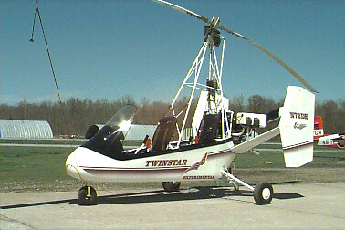 This is the demo Twinstar at Air & Space America,
in Paducah, Kentucky. See more here.
This picture is from their website, by the way.
This is the demo Twinstar at Air & Space America,
in Paducah, Kentucky. See more here.
This picture is from their website, by the way.
The Plan: Complete the Twinstar gyroplane fuselage within the next two months. During that time, acquire a Mazda 13B Rotary engine, preferably turbocharged, and modify it for mounting on this gyroplane. Modifications will include removing most of the sensors, and installing aviation-specific fuel and ignition controls from Real World Solutions. Along with this, I'll have to come up with engine mount and exhaust system designs and fabricate them (or have them fabricated). The propeller that I'm planning on using is the Warp Drive 68 inch, 4-Bladed ground adjustable, and the rotor is the RAF 30 foot, as recommended by Don Farrington at Farrington Aircraft. Remember, this is just a plan at this time, and is subject to changes.
Change 1: Make it three months. Got a trip in February (all month) where I'll be going through withdrawal.
Change 2: Trip in Feb didn't happen. Got a trip for three weeks in March, though. Same plan.
Change 3: 68" 3 Bladed ground adjustable is the propeller that I'm planning on using.
1 Jan 2000: Put a down payment on the basic Twinstar kit, hopefully to get the airframe in a couple of weeks. The structure is tack-welded, and needs final welding before I pick it up. Should be able to get that, landing gear, and wheels in a couple of weeks so I can clean it up and paint.
2 Jan 2000: Visited a few salvage yards, looking for 13B engines. Only saw one RX-7 in the 86 and later years, and it didn't have an engine. Found three in the earlier years, 80 to 85, but those have the 12A engines, so I'm thinking about trying to get one good one out of the three. Problem is, those are carbureted, not fuel injected, like the 13B, and don't supply as much power. Guess I'll keep looking for a 13B, and maybe get the 12A's to play with.
14 Jan 2000: They're still welding the airframe, so I'm thinking I'll get the kit next weekend. Called around to about fifteen salvage yards looking for a Mazda RX-7 post 1986. Almost lost hope, and called one more, and they have two, one 88 and one 90. One is crashed pretty bad, but the engine seems to be undamaged. The other looks like it drove in to the salvage yard. I told 'em I'd take them both. If nothing else, I'll overhaul one and replace all seals and gaskets, and just hang onto the other one. Next case, I'll combine the two and come up with one good one with new gaskets. Worst case, I'll combine the two, and have to spend another $1500 on gaskets, seals, and rotor housings, etc. We'll just have to see what they look like when I get them apart.
15 Jan 2000: Paid for the pair of
engines today, and they said they'd call me when they get them out and ready to
go. I asked for all coils, alternator, starter, and the oil cooler from
the un-crashed one. Hopefully they'll accomodate. Sounded like they
would. At least this gives me something to do while waiting for the gyro
kit!
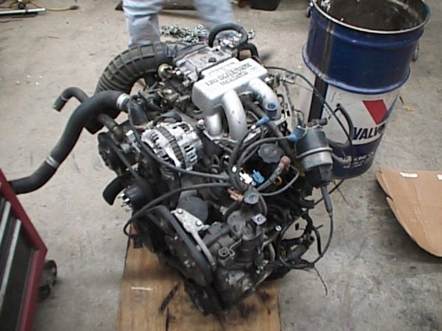
 This
is the engine out of the 1990 model RX-7.
This
is the engine out of the 1990 model RX-7.
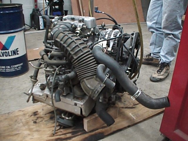
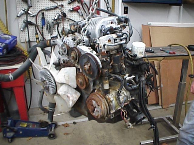 This
is the one out of the 1988 RX-7.
This
is the one out of the 1988 RX-7.
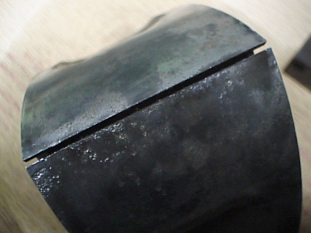
16 Jan 2000: The 1988 RX-7 engine (the
crashed one) had a rear rotor full of rusty water when we took it apart.
Might not be usable due to pitting, rust, etc. The rear and intermediate
rotor housings have surfacr rust (possible to lap the surface). Might be
able to salvage.
 Pretty
serious pitting on the rear rotor of the 88.
Pretty
serious pitting on the rear rotor of the 88.
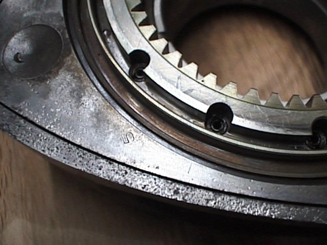 More
pitting on the side of the rear rotor.
More
pitting on the side of the rear rotor.
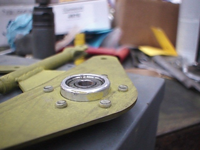
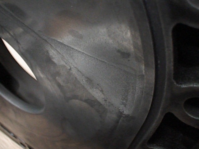 The
triangle is the rusty area where water had set for who knows how many
months. This is a no-go.
The
triangle is the rusty area where water had set for who knows how many
months. This is a no-go.
19 Jan 2000: After thorough washing of the intermediate housing of the 88, we found a crack where the left engine mount attaches to the bottom of the housing. Guess this is a no-go. The salvage yard worked well with me, and I ended up paying a total of $200 for that engine for parts. Well worth that. Switched over to the 90 model, which was in a car that drove in to the salvage yard. It has good compression, looks good, so I'll use it as is.
24 Jan 2000: Have the engine cleaned up
and all of the covers, bolts, etc, cleaned up. Put things back together
on the front of the engine, front cover, water pump, etc. Had to keep in
mind to make sure I didn't move or rotate the engine with the pulley hub off,
as the thrust bearings can be damaged (found out on the 88!). Painted the
cast iron pieces red, left the aluminum natural. Looks pretty good, but
you can tell that I painted it with it assembled. Oil injection system is
history; the pump will be blocked off with 1/4" aluminum plate, and the
oil ports are plugged with either JB Weld (intake manifold) or bolts/copper
washers (intermediate housing).
 Some
pictures of the "almost finished" engine, without oil pan, misc
parts.
Some
pictures of the "almost finished" engine, without oil pan, misc
parts.
28 Jan 2000: Cut away unnecessary
aluminum from the lower intake manifold, winding up with what actually looks
like an intake with runners, etc. Patched the valve actuator holes, after
cutting the excess aluminum off, with .032" aluminum sheet and
epoxy. This entire operation took me about 8 hours of cutting, grinding,
etc. Sure would be nice to have a milling machine for tasks like
this! Might be in John's future. He's wanted one for a while, and
this might be a good enough reason to pick one up.
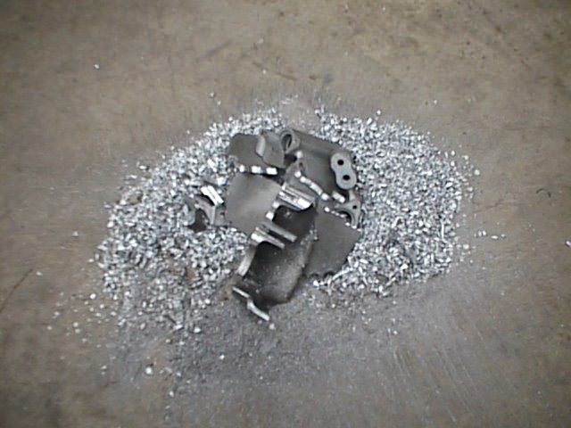 This
is what came off of the manifold! The pile is about 10 to 12 inches in
diameter.
This
is what came off of the manifold! The pile is about 10 to 12 inches in
diameter.
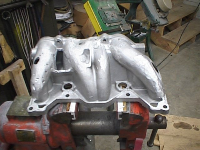 This
is the almost finished manifold, with the holes before the block-off plates
were epoxied on.
This
is the almost finished manifold, with the holes before the block-off plates
were epoxied on.
29 Jan 2000: Manufactured block-off plate for intake manifold to cover the exhaust ports (emissions controls). Entailed cutting the outline, precisely drilling mounting holes to match intake, and cutting the ports to closely match the intake ports. All in all, took about 7 hours of band sawing, filing, die-grinding, sanding, and bead-blasting. Looks pretty good if I say so myself. Also removed most of the vacuum ports and prepared to cover them with metal/epoxy.
30 Jan 2000: Took throttle body apart, cleaned up, and reassembled with minimal parts, and springs installed to fail open, not closed. Removed the outer/upper set of throttle plates/rod, and most of the stuff on the outside, and plugged unnecessary holes with JB Weld.
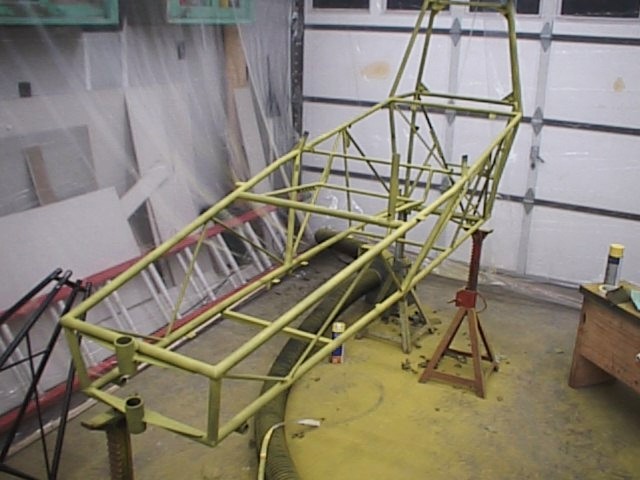
31 Jan 2000: Picked up the gyro kit this evening. Packed everything in the back of the truck and front seat. Talk about packed! The fuselage extended just past the tailgate hinge, as did the enclosure. The big pieces fit in the back, while everything else went in the front. It was pretty packed, to say the least. I got back from Paducah, and went directly to John's place to unload. He happened to be there (he was supposed to be on a trip), and helped move things around and make more room. I immediately started looking over the parts, sorting out what I would bead blast and zinc-chromate right off the bat. First task that I want to complete is to get the fuselage up on wheels and take it to get painted. This will be a great load off my mind. Several pieces got bead-blasted and primed tonight (toe brakes, rudder pedals, nose gear, etc.).
 Fuselage up on jack-stands, various parts hanging from the tower drying.
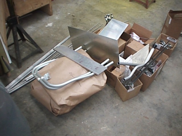 More
parts, etc.
More
parts, etc.
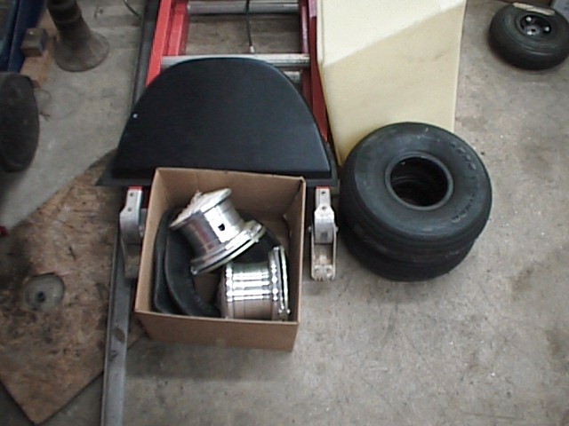 Wheels,
tires, instrument panel.
Wheels,
tires, instrument panel.
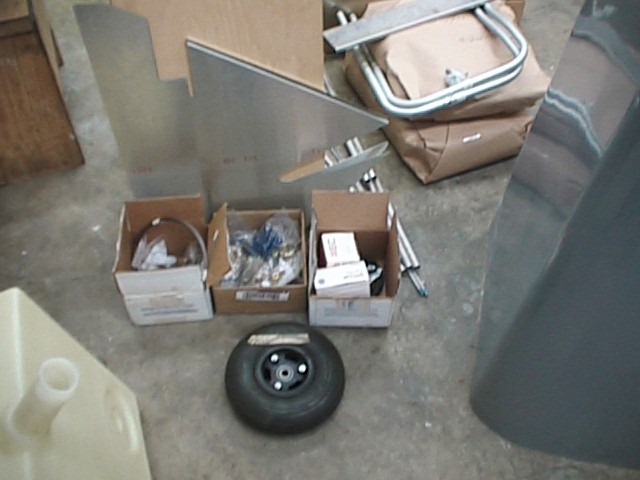 More
pieces parts!
More
pieces parts!
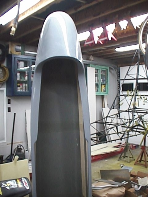 Fiberglass
enclosure (nicely done, I'd say. Only a little filling/finishing needed
on this.
Fiberglass
enclosure (nicely done, I'd say. Only a little filling/finishing needed
on this.
 Various
smaller parts after the primer has dried, just waiting to be final paited!
Various
smaller parts after the primer has dried, just waiting to be final paited!
1 Feb 2000: Continued bead-blasting
smaller parts that will fit in the cabinet, then priming them and stashing them
away. Continued the massive task of inventorying all of the parts for
each subsection. Of course, as I was inventorying, I'd notice little
parts that weren't too dificult to do, and that wouldn't take too long right
now, and went ahead and assembled them. The push-pull tubes for the toe
brakes and rudder pedals came about this way.
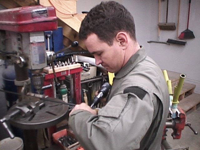 First
rivet being driven!! Brand new rivet gun, too!
First
rivet being driven!! Brand new rivet gun, too!
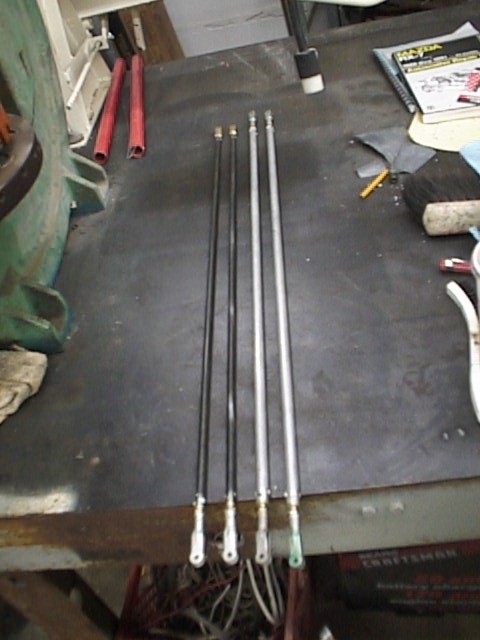 Finished
push-pull tubes.
Finished
push-pull tubes.
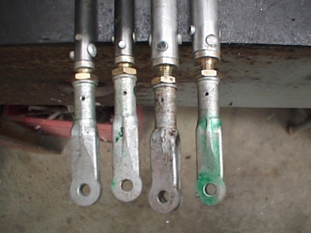 Rod-ends
closeup. Not the best rivets I've ever shot, but they'll do just fine.
Rod-ends
closeup. Not the best rivets I've ever shot, but they'll do just fine.
2 Feb 2000: Put up plastic around the
work area, so that my paint spray doesn't get all over everything in the
garage, like John's tools, motorcycle, etc. I figured that before I
started priming the fuselage, I needed some type of barrier. We took 1x2
lumber and drop cloths (plastic 10 x 20 ft, 1 mil), stapled the plastic to the
1x2's, and fastened them to the ceiling with drywall screws. We fitted a
blower with a couple of hoses, and ran the hose under the garage door for an
exhaust. Worked well for low volume painting. I'm planning on
taking the machine to a body shop for painting; I'd rather pay the money and
have it done right. At this point, I'm more concerned about rust than
looks. Anyway, primed the majority of the lower fuselage (didn't get to
the tower tonight). Sanded quite a bit, where there was slight surface
rust, then wiped everything down with lacquer thinner, and shot it with
zinc-chromate primer. Tomorrow I plan on priming the gear legs and
installing them, and hopefully getting the machine up on wheels.
 View
of the primed fuselage.
View
of the primed fuselage.
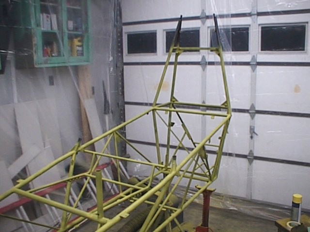 Another
view of the same.
Another
view of the same.
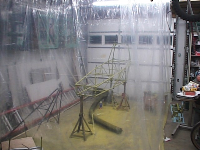 View
of the plastic barrier that we put up. Works pretty well so far.
View
of the plastic barrier that we put up. Works pretty well so far.
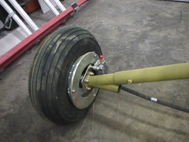
3 Feb 2000: Installed the landing gear
socket assembly, then the spring steel landing gear into the sockets.
That's some pretty tough stuff to drill! Finally figured out that very
slow RPM's and lots of pressure are required to drill those legs. Once I
changed my ways and slowed down, I had no more trouble.
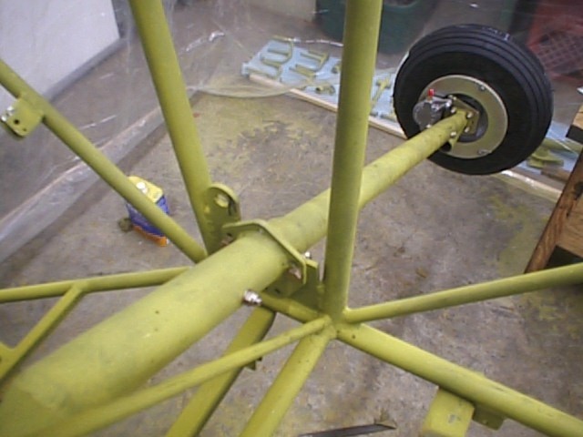 Left
landing gear area, showing socket attachment points to fuselage.
Left
landing gear area, showing socket attachment points to fuselage.
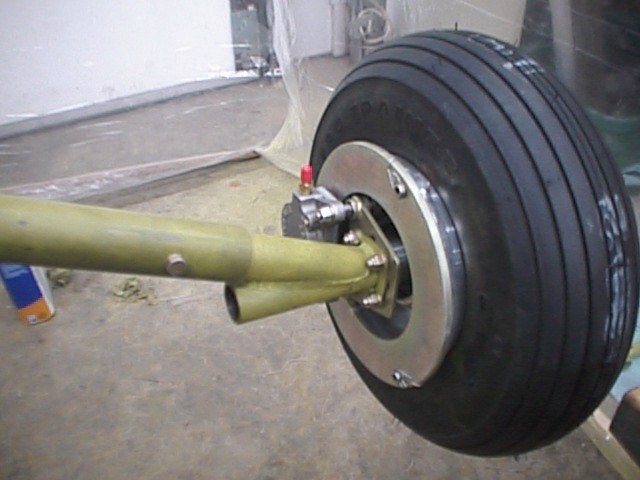
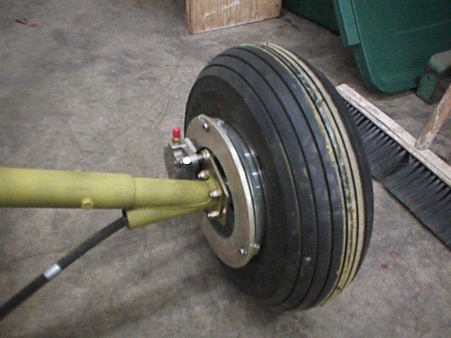
 Left
wheel with brake installed.
Left
wheel with brake installed.
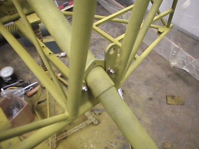 Left
socket/landing gear.
Left
socket/landing gear.
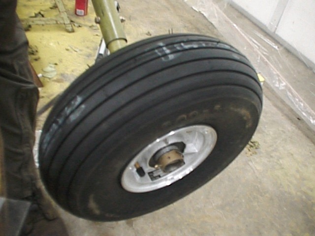
 Right
landing gear, without wheel or brake installed.
Right
landing gear, without wheel or brake installed.
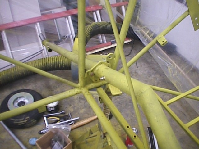
4 Feb 2000: Installed the
pedals/interconnecting pushrods, rear seat bottom (temporarily for painting),
right brake and main wheel, nose gear. All of this went relatively
smoothly, no hitches. After I was done with these tasks, I went ahead and
installed the bellcrank bearings into the bellcranks, which was pretty
fun. I enjoy any riveting that I get to do on this machine.
 Front
pedal installation, with nose gear visible..
Front
pedal installation, with nose gear visible..
 Rear
pedal installation.
Rear
pedal installation.
 Left
gear with brake hose installed.
Left
gear with brake hose installed.
 Right
gear with brake hose installed.
Right
gear with brake hose installed.
 Misc
pictures of the bellcranks.
Misc
pictures of the bellcranks.
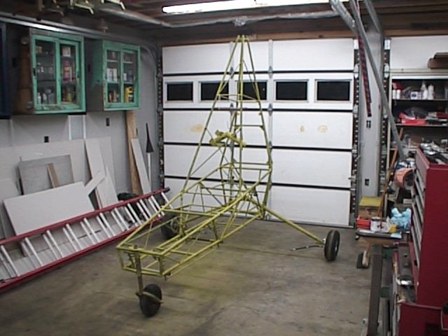
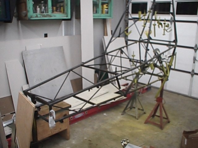
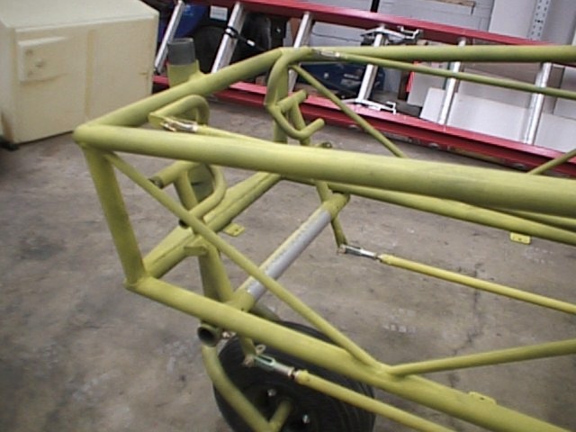
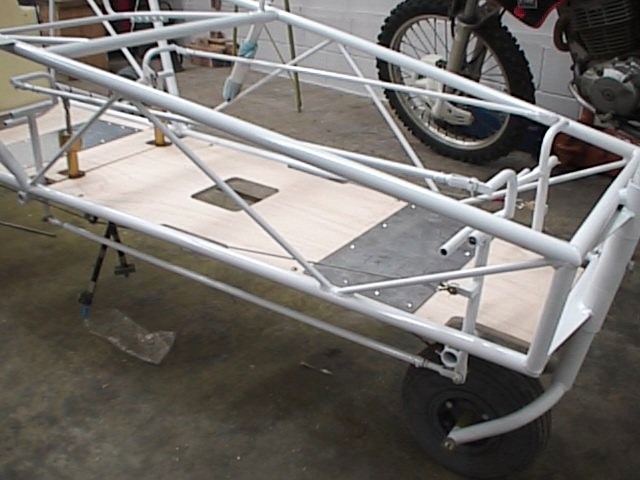
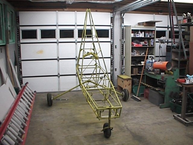 Finally
up on wheels!! The part on the tower is the tail support, with primer
drying.
Finally
up on wheels!! The part on the tower is the tail support, with primer
drying.
5 Feb 2000: Not a whole lot happened today, just cleaned up a little, rolled the plastic up and attached it to the ceiling for later use. Swept (or attempted, anyway) to sweep the zinc-chromate primer dust from the floor, and straightened up a little. I'm about to the point of getting this machine painted, but still haven't decided who will do it. I'd RATHER paint it myself, if I can find a booth.
8 Feb 2000: I decided to have the fuselage painted by a painter up here in Hopkinsville, KY. Pretty good deal to get it done professionally, and I'll be paying less than I would if I rented the paint booth on Fort Campbell for a DAY. It's in the shop now, should be out this weekend, then I can get down to some real assembly.
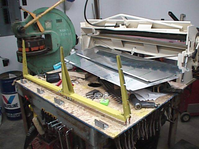
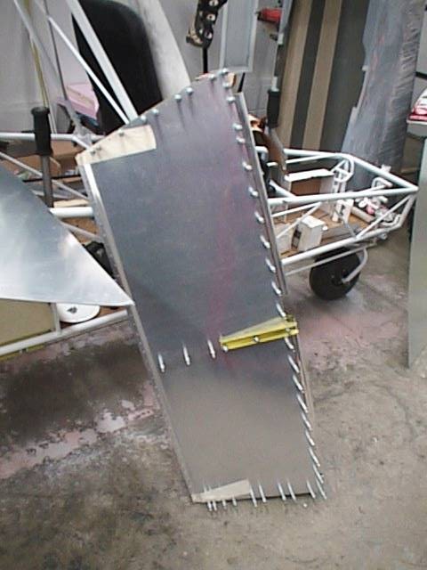
10 Feb 2000: I happened upon a metal shear that will cut my 1/4" x 24" x 48" sheet of aluminum. This plate will become my mounting system for the engine, once I dress it up and cut some holes in it. Believe me, it takes a pretty good size shear to cut this stuff.
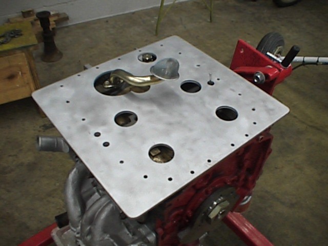
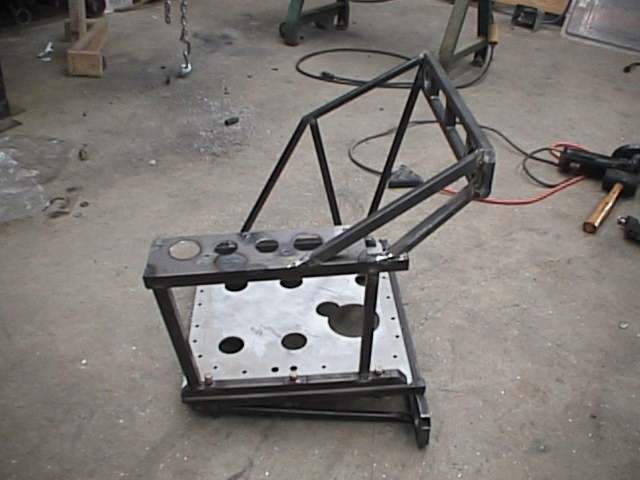
11 Feb 2000: Finished up the engine
mount plate and bead-blasted it. Now, I need to come up with a system to
connect that assembly to the rear of the fuselage, and work some isolation
mounts in there somewhere. Also fabricated the cover plate for the oil
injection pump that I removed in favor of pre-mixing oil with gas. This
cover, also, is made from 1/4" aluminum plate.
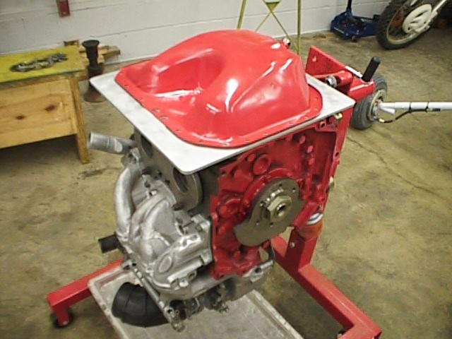 Engine
mount plate as it will be installed (engine inverted).
Engine
mount plate as it will be installed (engine inverted).
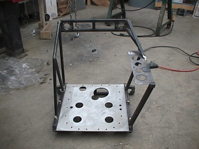
 Better
view of the 1/4" aluminum plate.
Better
view of the 1/4" aluminum plate.
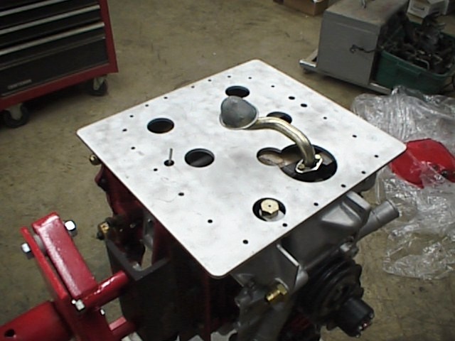 One
more view.
One
more view.
12 Feb 2000: Took a trip to Paducah today to pick up some more parts, mainly miscellaneous nuts and bolts that I had messed up (inch-lbs, not foot-lbs!), or that weren't included due to changes in the kit over the last few weeks or so. Picked up some engine isolation mounts, and checked them out when I got back to John's, and believe they'll work very nicely. Now I have some points to start with for the structure of the mount itself. All of the dots are there; I just have to connect them. I ordered the rotor blades today from Don Farrington (RAF 30'), also. The fuselage should be ready to pick up tomorrow morning.
13 Feb 2000: Got the fuselage back from
the paint shop today. He did a heck of a lot better than I could have,
considering I'd have runs all over the thing. I already had several runs
in the primer, so I didn't want to tackle the paint booth issue. He gave
me the rest of the can of white paint, and I got an air brush that did a
fantastic job of throwing some more paint on the spots he missed. There
were a few light spots, but the majority of the machine looked good. Like
I said, much better than I could have done. Once back at John's, I
started in on brake lines and standoffs. I got the external lines done
and mounted, but cut a little too much on one of the internal lines and it
ended up too short, so I'll have to get some more aluminum line. No big
deal.
 Left
brake lines with standoffs. Those standoffs are old rubber hose...
They'll get replaced with clear tube.
Left
brake lines with standoffs. Those standoffs are old rubber hose...
They'll get replaced with clear tube.
 Right
exterior brake lines with standoffs.
Right
exterior brake lines with standoffs.
The next task was the rudder controls. I
already had the stabilizer socket installed for painting, and left it in for
the bellcrank installation. I'd recommend installing the bellcranks with
the socket assembly off of the fuselage. The washer stackup was difficult
at the weird angles; the way I worked that out was to install the bolt from the
bottom, carefully placing the two spacer washers on the bolt, then the
bellcrank, then the top two spacer washers, and pushing the bolt on up.
Then, I took a -416 washer on another pivot bolt and pushed the first bolt
(upside down) out with the second bolt. This one is now installed the correct
direction. I then put the lower -416 washer and self-locking nut on, and
that one was done. I did the same type of thing for the rear pulleys,
also. This is the first time I've done cables, but they turned out pretty
good. The first two ends that I made didn't come out the best because I
didn't grind down the points on the thimbles. The rest of them worked
very well, as I ground the points off. Centering and locking the tie-link
was accomplished by taking a 1/2" by 4 1/2" (approx) piece of .032"
aluminum and drilling two 3/16" dia holes on 3 13/32" (I believe...
can't remember now) centers. These pieces then fit between the bellcrank
input pins and the pulley pivot bolts. They both fit in without further
alteration, and locked that section in place. The forward pedals were
done with wood blocks and c-clamps, so they wouldn't move at all. I ran
the cables, cut off the excess, and shrink-wrapped the ends to prevent fraying.
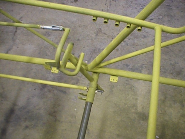
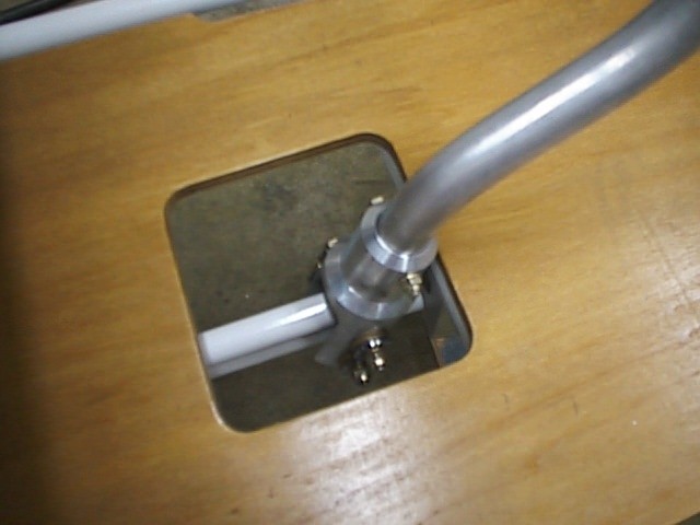
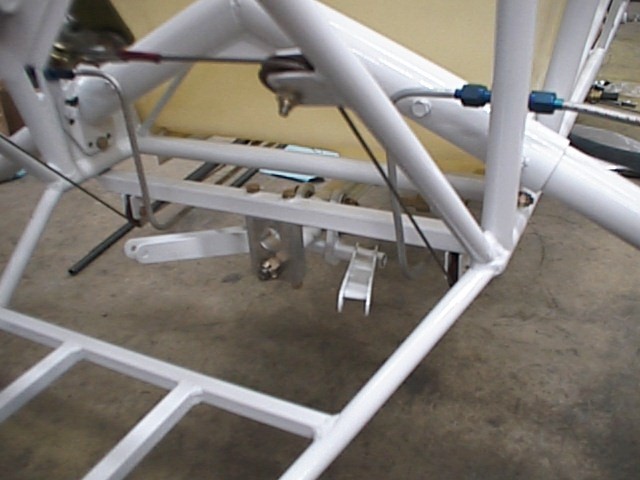
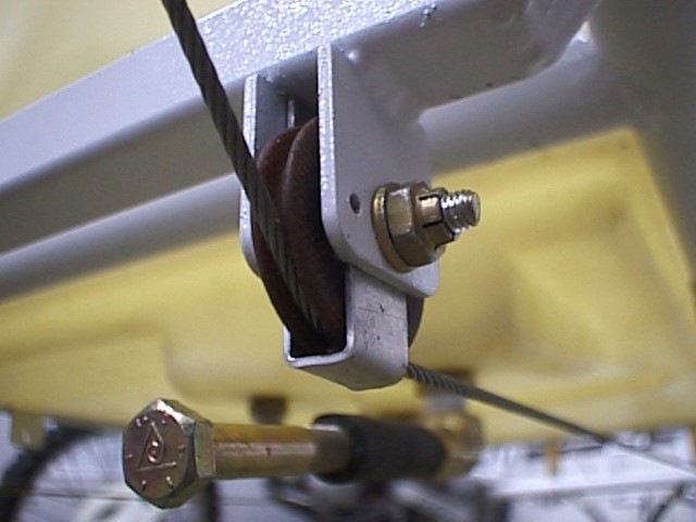 Second (middle) pulley on right side. I
fabricated the keeper that goes around the pulley/cable. The bolt that
you see is to plug the fuel tank for leak tests.
Second (middle) pulley on right side. I
fabricated the keeper that goes around the pulley/cable. The bolt that
you see is to plug the fuel tank for leak tests.
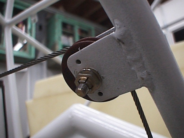 Third
(rear) pulley on right side.
Third
(rear) pulley on right side.
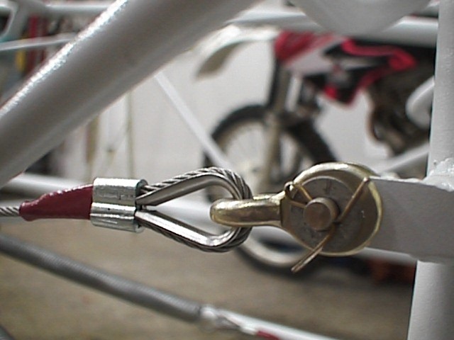 Cable
connection to right forward rudder pedal.
Cable
connection to right forward rudder pedal.
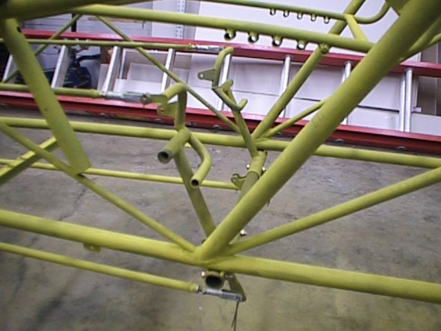
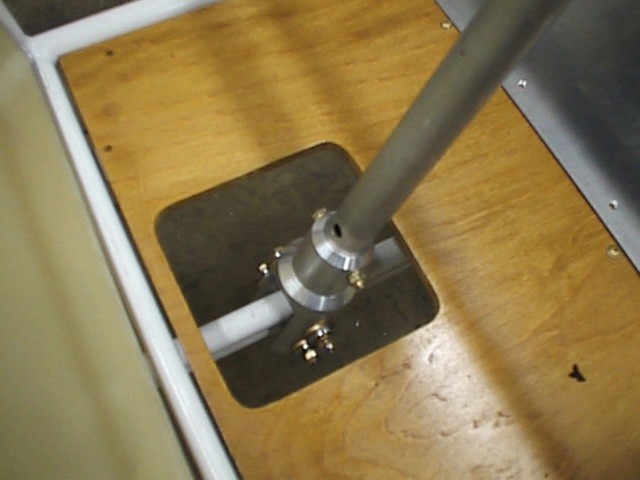
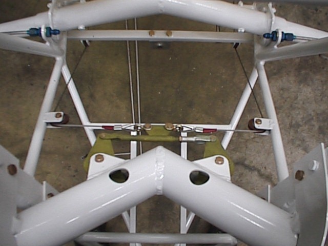 Rudder
tie-link installed, looking down from rear of fuselage.
Rudder
tie-link installed, looking down from rear of fuselage.
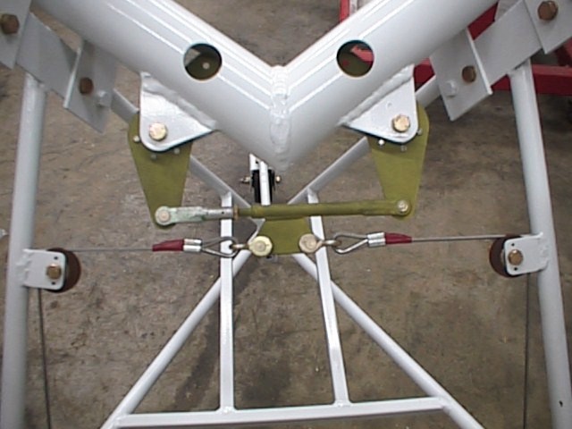 Tie-link
looking down from front of fuselage.
Tie-link
looking down from front of fuselage.
14 Feb 2000: All evening I worked on
the wood floorboards and sheet aluminum scuff panels. They came out
pretty nice, as you can see by the photos; I'm pretty happy with both of
them. The cutouts in the manual are pretty accurate, but still needed
quite a bit of tailoring to fit around the pedals without contact. Most
of the cuts I made with a bandsaw, but used a router with a plunge bit to cut
out the holes for the cyclic sticks. Very carefully, with the router, I
trimmed the wood up to my pencil lines and sanded, once the cutouts cleared the
controls. The front scuff panel needed some trimming because of the taper
of the fuselage, and I just laid the piece between the lower longerons, and set
a 6" machinist's rule along the longeron on each side, to mark a 1/2"
clearance for a cut line, so the edges of the panel parallel the
longerons. Spaced the holes around the panel, drilled 1/8" holes and
countersunk for the short countersunk screws. Very tedious, but enjoyable
work. I plan on sealing floorboards with sanding sealer, then staining
with a dark stain. Should look nice.
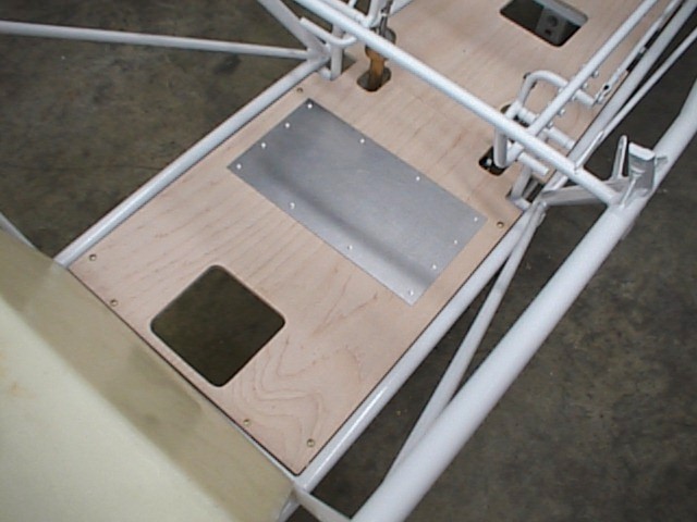
 Pictures
of the rear floorboard and scuff panel, screws not installed.
Pictures
of the rear floorboard and scuff panel, screws not installed.
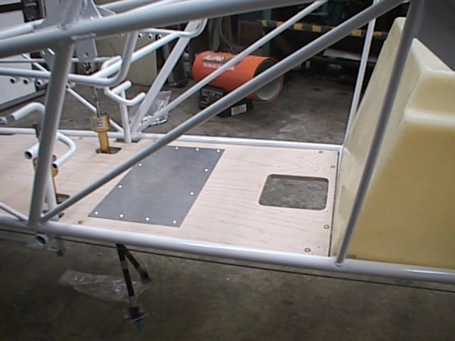
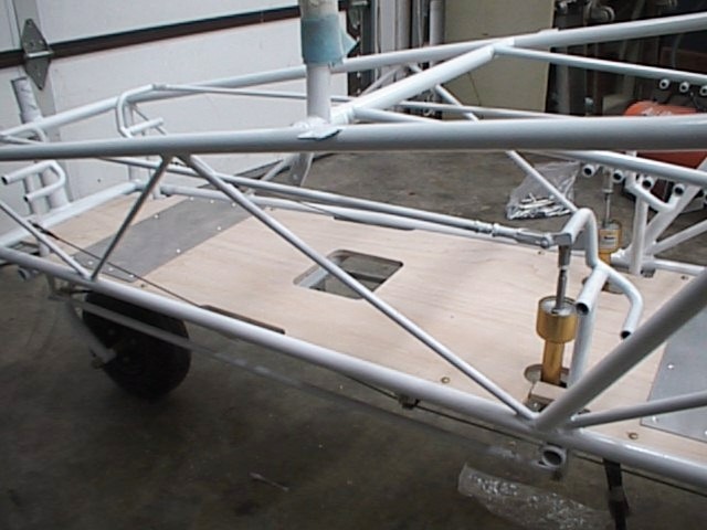 Shots
of the forward station floorboard and scuff panel.
Shots
of the forward station floorboard and scuff panel.
18 Feb 2000: Sanded and stained the floorboards, and sealed them with a spray-on exterior sealer. Installed the front floorboard, but haven't permanently installed the rear, due to the fuel tank not being completely installed yet.
19 Feb 2000: Went to Paducah and picked up the flight control torque tubes and mixing unit. Disassembled the unit and painted the tubes and mixer. Assembled the control tube sockets and control sticks, which was more of a major undertaking than I figured it would be. The control sticks were just about exactly the same size as the socket, so it would go in easily, but the metal would gall and lock up, where the stick wouldn't come out. With quite a bit of sanding and wire brushing, I got the clearance where it should be, and they go in and out fine.
Also received the rest of the parts for the
seats, and built the seat backs. This was very straightforward, and the
seat covers fit perfectly. I haven't built the back seat bottom yet,
because I don't have the fuel tank mounted yet. Still dreaming of a plan
for that. At least I can sit in the front seat and act like I'm flying!
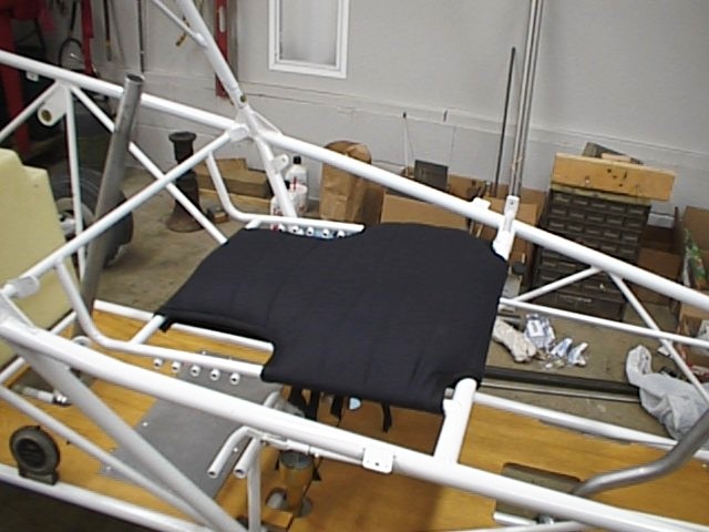 Front
seat bottom cushion
Front
seat bottom cushion
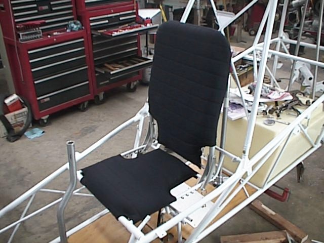 Front
seat completed. Pretty nice installation for the seats.
Front
seat completed. Pretty nice installation for the seats.
20 Feb 2000: Reassembled the torque
tubes and control sticks, torqued all bolts (AN4), and torque-sealed them.
 Front
and rear control stick installations.
Front
and rear control stick installations.
 Various
control installation shots.
Various
control installation shots.
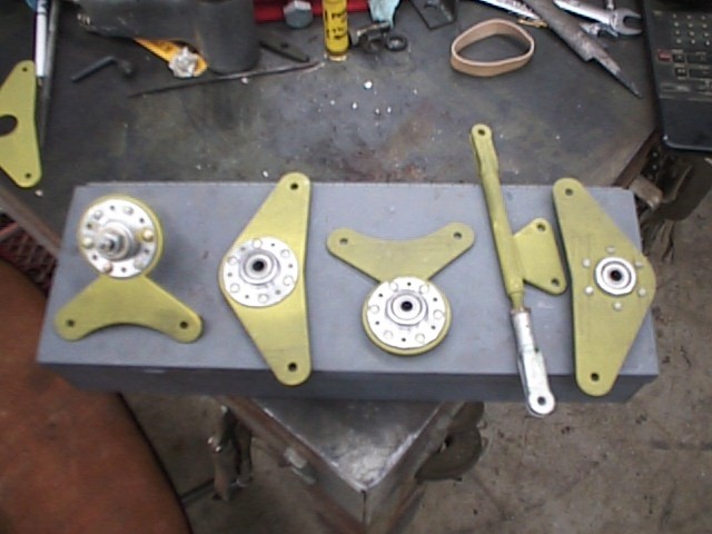
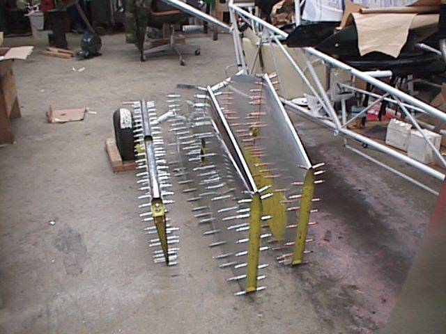
23 Feb 2000: Assembled the lower rotor
push-pull tubes from aluminum tube, aluminum rod end inserts, and adjustable
rod ends. These were basically the same as the earlier ones, for the
rudders and brakes. Not a big deal. The tubes were already cut to
length, so all I had to do was drill three holes (plus a witness hole) per end,
and shoot #4 universal rivets to fasten the rod end insert.
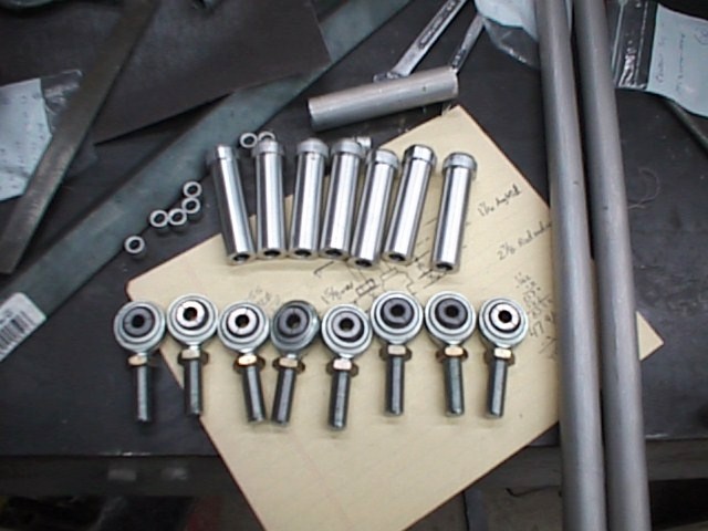
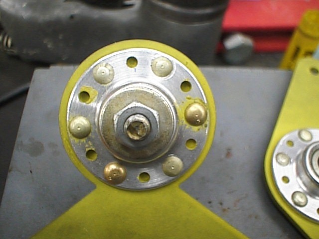
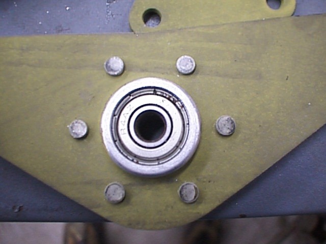
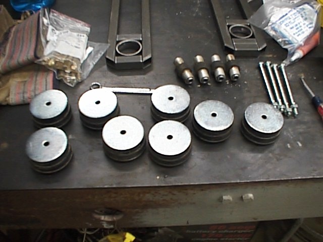
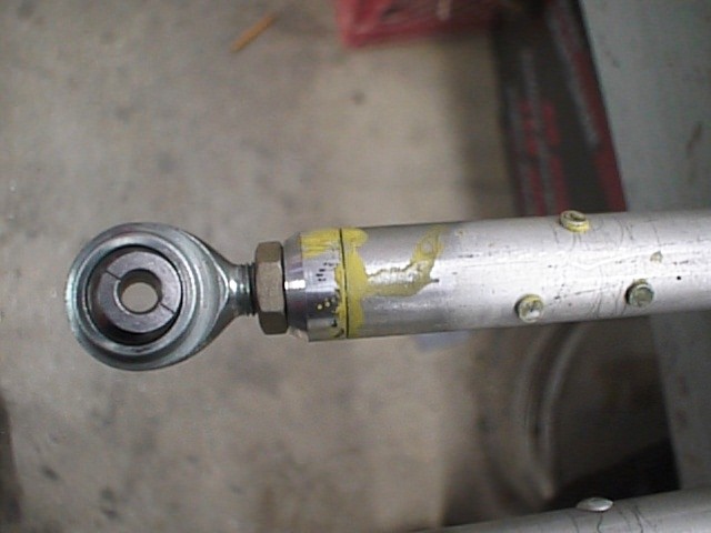 Pushrod
pieces, and a completed rod end for the lower pushrod.
Pushrod
pieces, and a completed rod end for the lower pushrod.
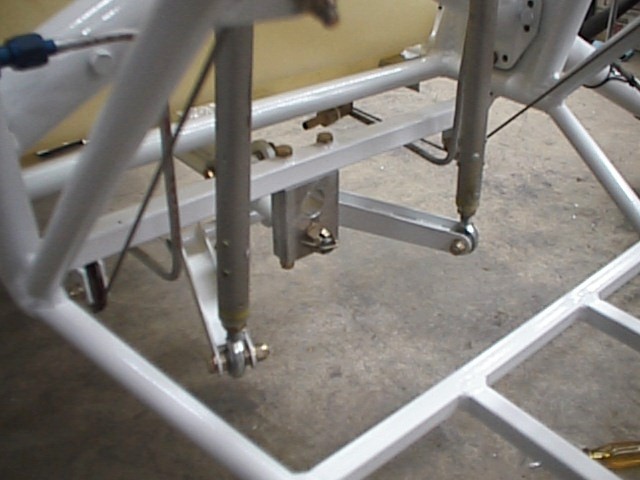
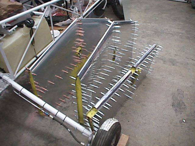
 Lower
pushrods installed to the mixing unit and idler arms.
Lower
pushrods installed to the mixing unit and idler arms.
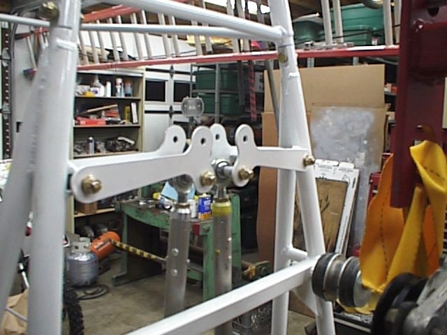
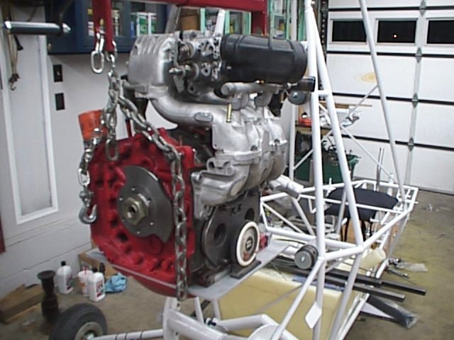
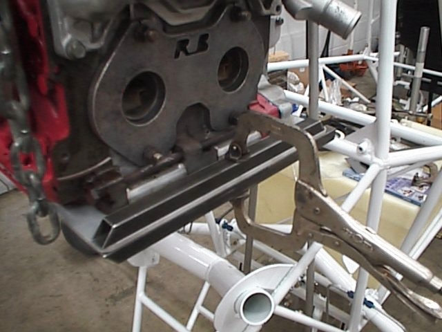
26 Feb 2000: Hung the engine where it
needs to go, started dreaming of ways to attach that thing to the back of the
machine. Ended up trying to dream up a way for about a week, and finally
decided on a method. Might be more complex than most people would go for,
and I think if I have to remount the engine, I'll go with a method that doesn't
require quite so many welds.
 Mmmmm.
This looks about right. I did measure some things!
Mmmmm.
This looks about right. I did measure some things!
1 Mar 2000: Started cutting pieces for
the engine mount. My plan is to use the isolation mounts at the front of
the engine mount, and mount the engine hard to the mount. The 1/4"
aluminum plate will get sandwiched between the upper and lower mounts. I
borrowed a friend's portable MIG welder so that I could tack weld the
assemblies on the aircraft. Throughout, I had the smaller individual
assemblies (forward upper, forward lower, and the upper and lower rear
assemblies) TIG welded by a friend, so that I could temporarily mount them, and
know that's how they would go together at completion.
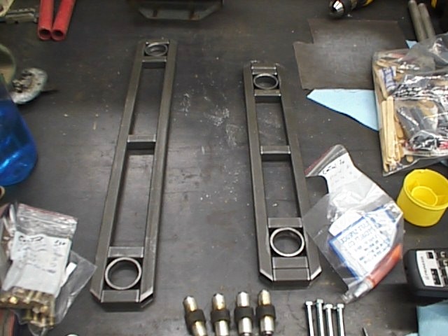
 Individual
parts for the upper forward and lower forward sub-assemblies.
Individual
parts for the upper forward and lower forward sub-assemblies.
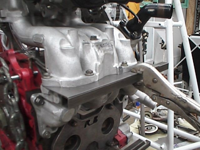 Interesting
part here. A plate actually is attached through the intake manifold.
Interesting
part here. A plate actually is attached through the intake manifold.
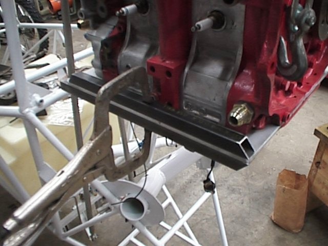
 Right
and left lower rear mount assemblies.
Right
and left lower rear mount assemblies.
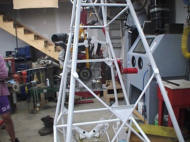
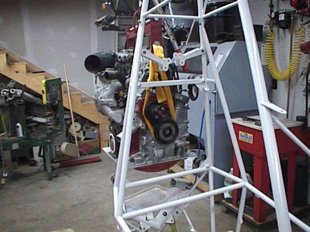
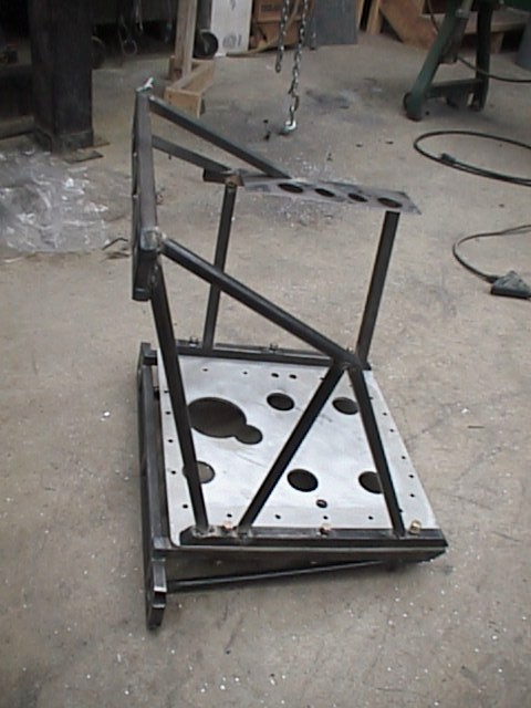
9 Mar 2000: Finished cutting my pieces,
and tack welded everything together. For the first time, the engine was
off of the hoist, and actually mounted to the aircraft for a few minutes.
I didn't leave it there long, as the welds were only tacks, but it did support
the engine.
 Tack
welded engine mount, complete.
Tack
welded engine mount, complete.
 Assembled
mount, left side, with plate installed.
Assembled
mount, left side, with plate installed.
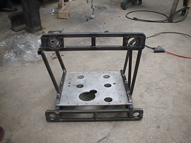 Front
view.
Front
view.
 Right
side view. Notice the plate that gets sandwiched between the intake
manifold parts.
Right
side view. Notice the plate that gets sandwiched between the intake
manifold parts.
 Rear
view.
Rear
view.
11 Mar 2000: Final welding is complete on the engine mount as it will go on the aircraft. What a load off of my mind! Now it gets painted and installed.
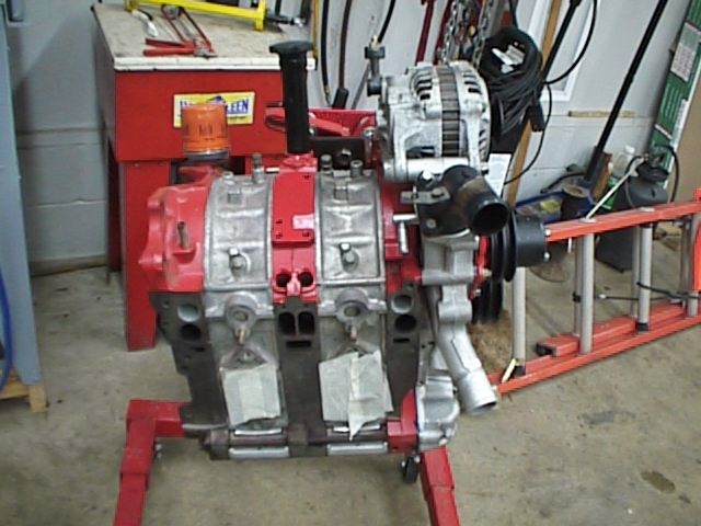
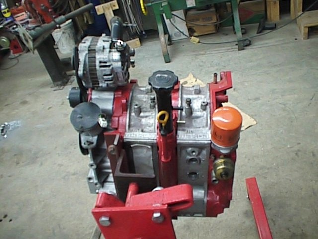
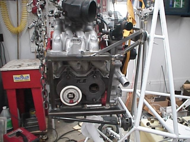
12-14 Mar 2000: Painted the engine
mount, and mounted the engine. Looks pretty good.
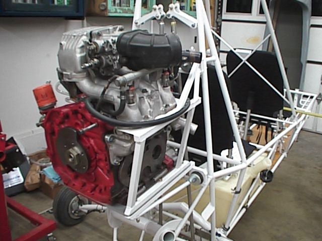
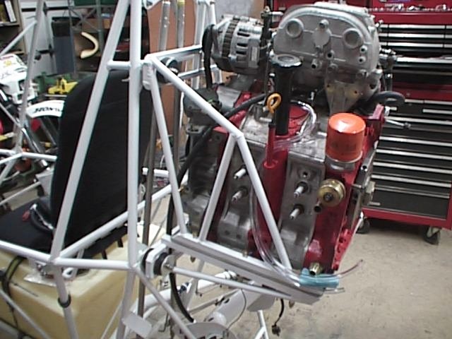 Right
and left views of the engine, mounted on the airframe.
Right
and left views of the engine, mounted on the airframe.
15 Mar to 8 Apr 2000: Been working on the gyro on and off, staying up late, getting in late, and not taking many pictures or updating these pages. I have several pictures on disk, but haven't worked on them to get them on the page. I'll keep working on that, and will have them up one of these days.
During this time, I built a sort of "firewall" in front of the engine to mount accessories on, and to put something between the passenger/push-pull tubes and the dual accessory drive belts on the engine. Also, the coils are mounted to the left and right sides of the fuselage behind the passenger seat, to .050" aluminum sheet panels attached by DG-14 cushioned clamps.
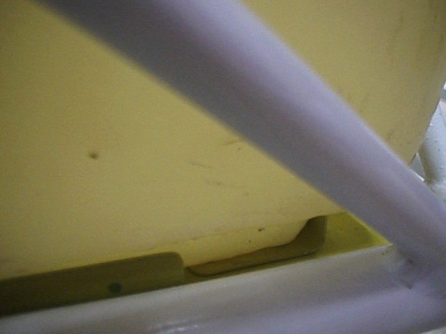
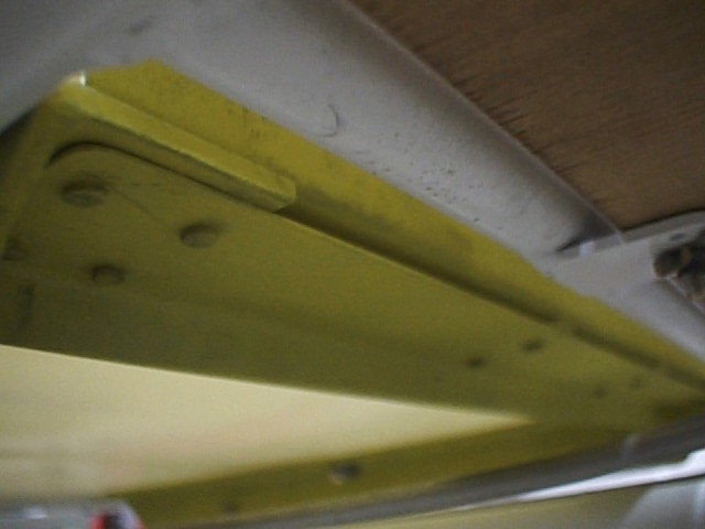
I accomplished fuel tank mounting by
fastening 1 1/2" square angle on each side of the fuselage under the back
seat, to the tabs, as designed. The forward ends of the angle are
fastened together via angle sheet across the front on top and bottom, with 2
each 1/8" spacers in the middle. This was riveted together with
flush rivets. The sheet angle on top was positioned to restrain the tank
from forward movement. On the sides, more formed angle was riveted to
restrain side movement, and two smaller pieces at the rear of the 1 1/2"
angle for rear restraint. The fuel tank fits securely into the fitted
angles. I took care of upward restraint by using two turnbuckles attached
to DG-14 cushioned clamps around the lower frame rails, up to a 1" strap
of .040" thick 4130 steel. This strap is encased in a rubber channel
from Wicks, designed just for this. The strap runs across the top of the
tank, pre-bent for the corners of the tank, and attached to the turnbuckles
with clevis pins/washers/cotter pins. The turnbuckes are tightened up
evenly, and everything is very secure.
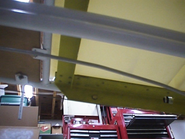
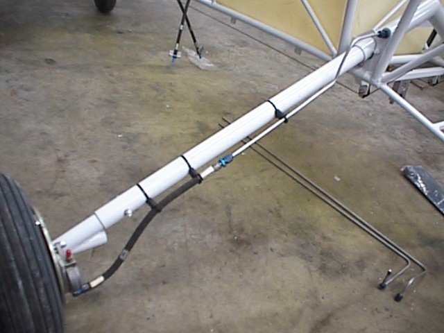
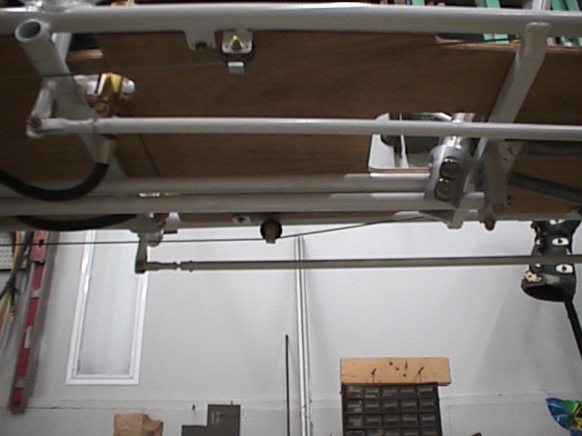
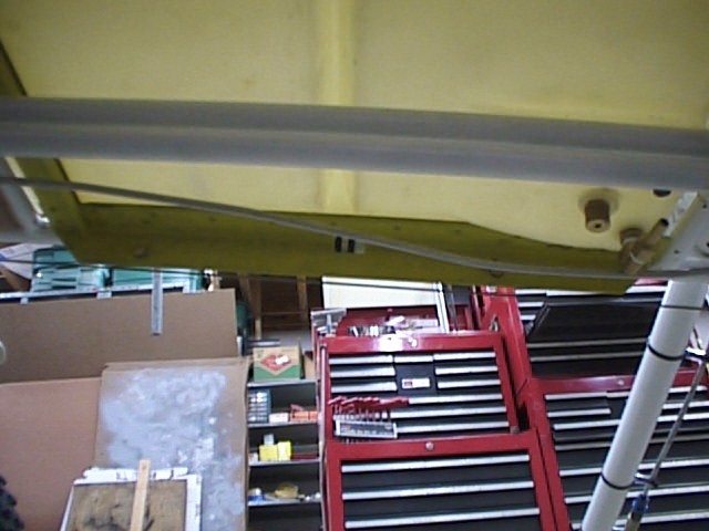 Bottom
right side from underneath.
Bottom
right side from underneath.
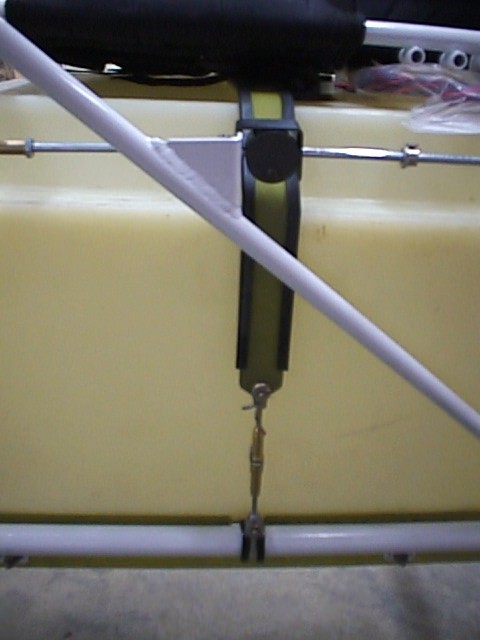
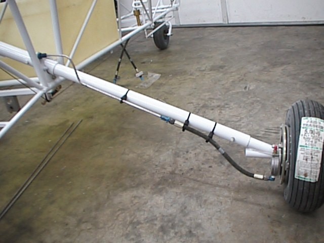
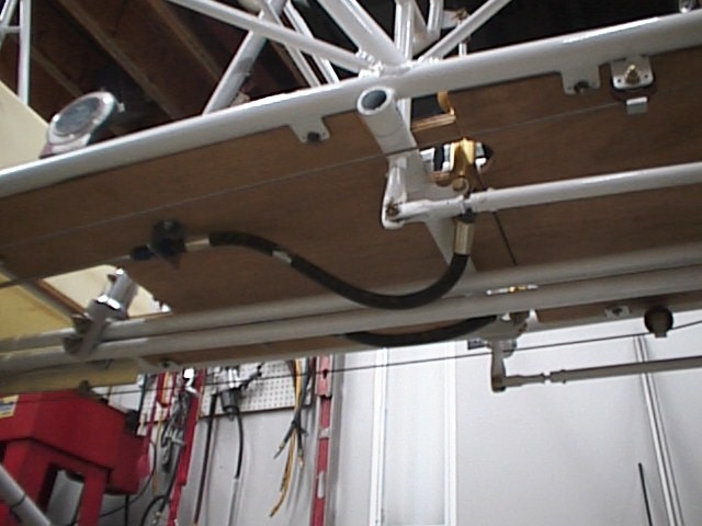
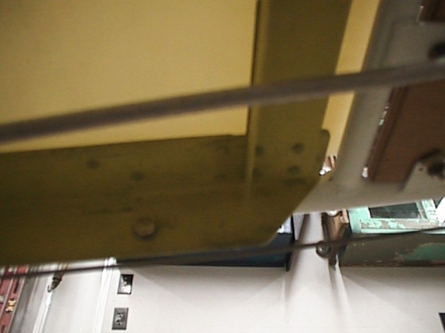
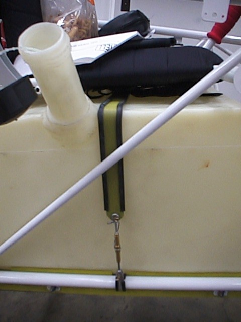 Strap
and turnbuckles, left then right side.
Strap
and turnbuckles, left then right side.
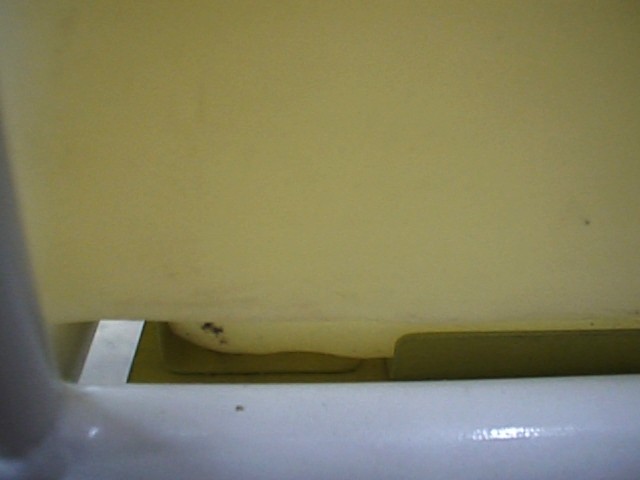
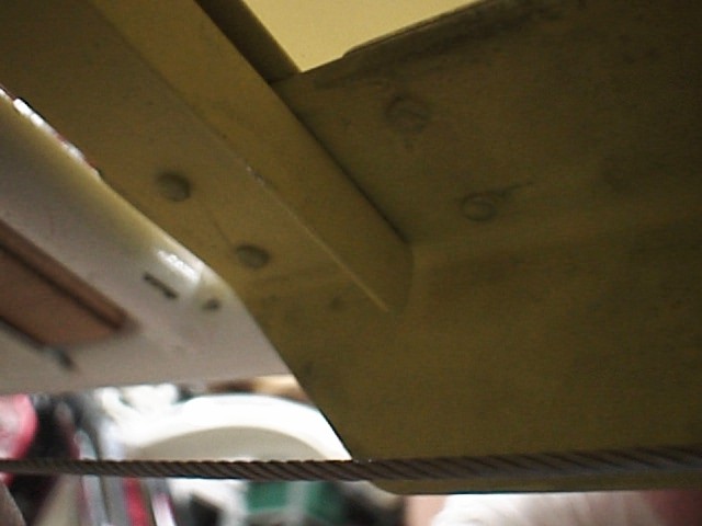
 Angles
from above, showing engagement on step of tank.
Angles
from above, showing engagement on step of tank.
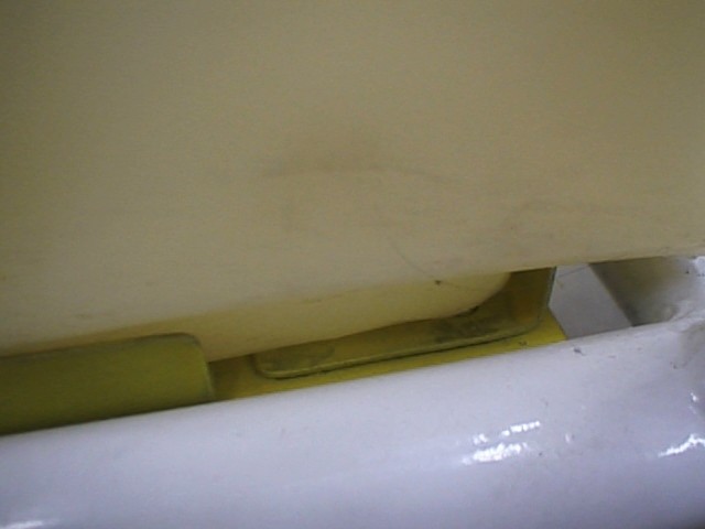
 Front
angles, showing two spacers.
Front
angles, showing two spacers.
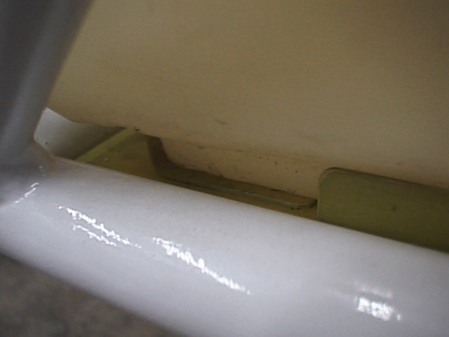
 Front
right corner, and front left corner from bottom.
Front
right corner, and front left corner from bottom.
9-10 Apr 2000: Went to Paducah and got schooled up on the changes that went into the tail section. Got a good part of it built, and will continue to work on the tail sections when I get back home.
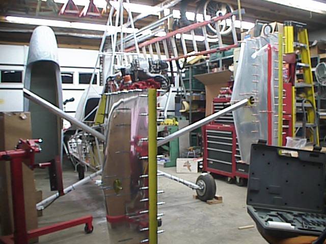
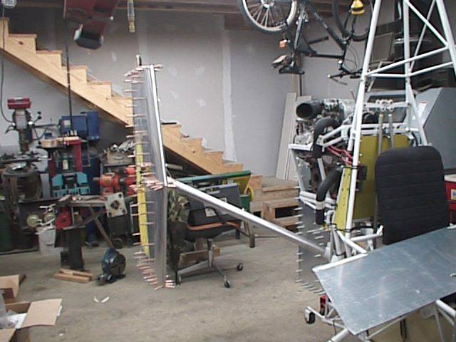
11-22 Apr 2000: Continue to work on the tail sections. The vertical stabilizers are built, ready to rivet, once I get the holes ream-drilled to #30. After buying around 300 Clecos of 3/32 and 1/8 inch, I finally have nearly enough! Man, takes a bunch to do it right. I'm waiting on some nutplates before I build up the horizontal stabilizers, as the one I received weren't correct. I've got the correct ones ordered, and will continue with the the horizontal stabs once I receive those. I have all of the parts required for the rudders, and just need to put them together and rivet them up.
 Vertical
stabilizers temporarily assembled, with one rudder.
Vertical
stabilizers temporarily assembled, with one rudder.
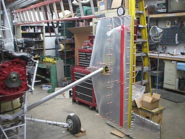 Various
pics of vertical stab.
Various
pics of vertical stab.
 Rudder
frame, and temporarily assembled rudder.
Rudder
frame, and temporarily assembled rudder.
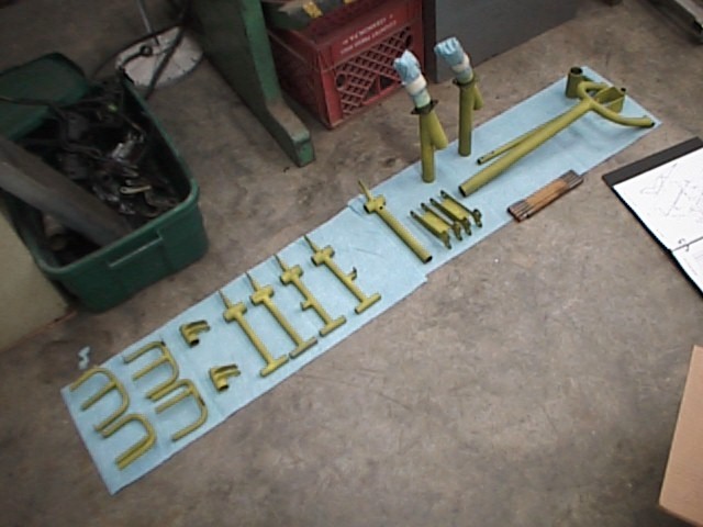
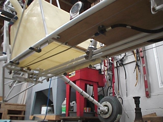
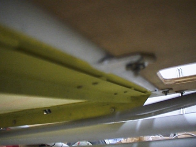
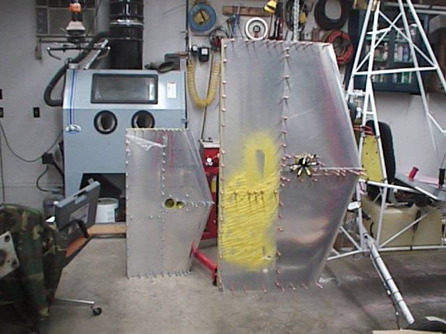
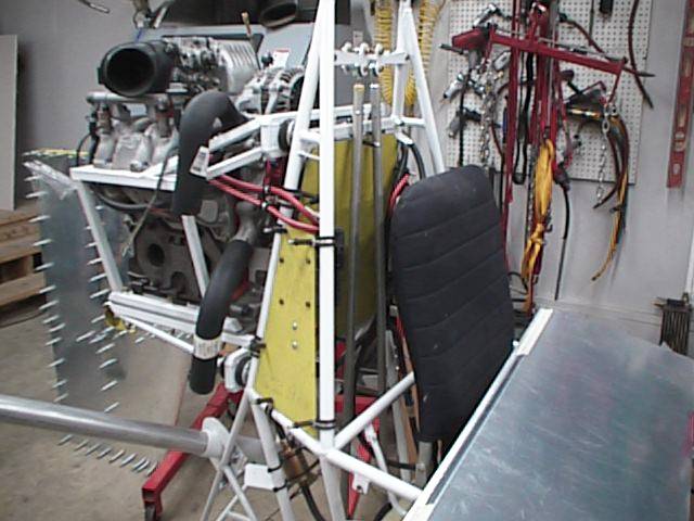 Yellow
panels on sides have the coils mounted to them.
Yellow
panels on sides have the coils mounted to them.
Another issue that I was waiting on for the
vertical stabilizers was a spacer through which the bolt passes and clamps to
the horizontal stabilizer. Nothing was shown, so I queried Farrington
Aircraft, and came up with an idea of using a 3/4" x 1" x 1
15/16" block of aluminum, epoxied between the nose ribs, centered on
the cutout hole for this bolt. Once this assembly is glued up fast and
everything is aligned, I started a hole in the block, centered in the cutout in
the ribs (round cutout about 3/8" diameter). Making sure it was
perpendicular (easy to do with a #30 x 6" bit), I drilled about half way
down. Turned the stabilizer over, and started on the other side, until
the holes met in the middle. Reamed them with a few passes from the
drill, then drilled again once through with a #10 bit. It should be
possible to bolt this up tight without fear of crushing the vertical
tail. Now, it's ready to put together for the last time.
26 Apr 2000: Assembled the left vertical stabilizer with solid rivets where I could get them in, and Cherry Max for the blind areas. Total rivets used for a single vertical stabilizer was approximately 370. I used 122 Cherry Max 4-2 rivets, which was more than I had planned on for the entire tail. Getting expensive, buying those things. I trust them a whole lot more than pop rivets, though. Having been a sheet metal guy when I was enlisted, I know that they work, and that they're strong. I believe it's worth the price, though. The foam core (2" thick insulation) is double-sided taped, and the skins are double-sided taped, and then the thing is very carefully aligned before any of the tape touches other tape. The rear outboard skin didn't go on very smoothly, and I had to redo the tape. Second time was a charm. The first nose skin went on smoothly, but the other one was a problem, just because the foam kept tilting out and touching the skin. Finally went together and the rivets went in, until I ran out of blind rivets. Needed 22 4-2s, and 9 4-3s. Other than that, the stabilizer went together pretty well.
27 Apr 2000: Took the stabilizer to work and used one of the Cherry Max pullers to pull the last 31 rivets. Borrowed rivets from a DynCorp guy until my next order comes in. I've got plenty of 4-1s, ordered 150 of those, then used about 20. Ordered 100 4-2s, and used them all, plus 22, on the first vertical stab. Didn't order any 4-3s, need 9 per stab. I think I've got plenty ordered, now.
Shot the solid rivets in the right vertical stabilizer, taped the rear foam, and assembled the second skin. Ran out of time, and had to leave the assembly as it was. Tomorrow I'll finish up the right vertical stabilizer, and, time permitting, mount them on the airfram so I can build the horizontal stabilizers to fit in place.
Assembled the nut plates and fittings onto the tip ribs for the horizontal stab. Once I get the vertical stabs installed and bolted straight, I'll temporarily install the tip ribs for the horizontal stab, bolted in place, just like they'll be when finished, then take my measurements, or just build the stabs using the aircraft as a jig. Might be tricky, but at least the parts will be a guaranteed fit. We'll see how it all works.
NOTICE: